Difficulty: Intermediate (soldering required)
Time: Around 2 hours
MIPR is a modular robot that will allow you to design sensor boards depending on what functionality you need from the robot. After experimenting with robotics I found that once a robot is built it can be hard to add functionality so I designed MIPR to overcome this challenge. If extra functionality is required the base robot can stay the same with the base code and new sensor boards can be designed reducing development time. This tutorial will take around 2 hours to complete and is accompanied with a You Tube video.
For an in depth step by step guide on building this robot watch the You Tube video the below instructions are their as a quick guide on building the robot where as the video is more of a tutorial. I recommend having the schematic printed out when following the video.
I will be publishing another tutorial that will show you how to make a battery board for MIPR. This will be a board powered by a single cell LiPo and will be chargeable though USB negating the need for a LiPo battery charger.
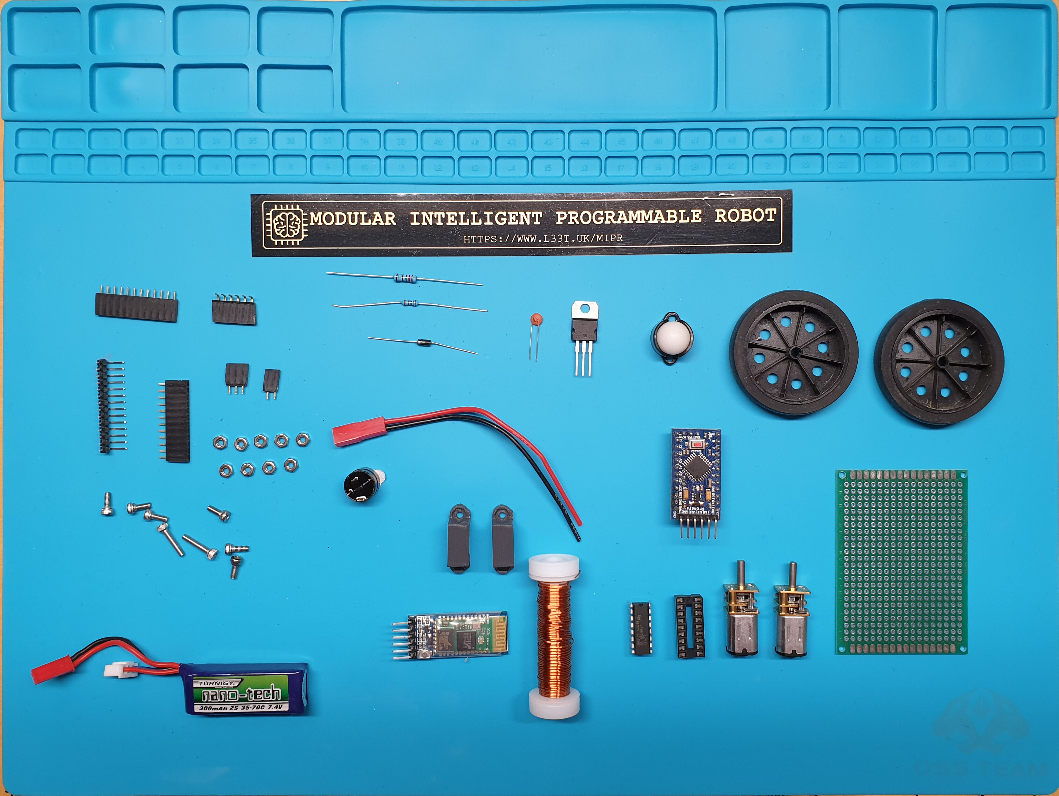
Components Required
- Perfboard 5cm by 7cm.
- HC-05 bluetooth serial module.
- Arduino Pro Mini (This design)
- N20 6v or 12v motors 240rpm (Example)
- 2 wheels that fit on the N20 motors (Example)
- Battery (see options here), I used a 2S LiPo. (Example). If your going to follow the battery board tutorial this is not required.
- 1/2″ Caster wheel (Example)
- Piezo buzzer (Example)
- L293D
- 16 DIP socket (for L293D). I used a 18 DIP ones as it was all I had.
- N20 brackets to hold motors. I 3D printed them otherwise they can be purchased here.
- 7805CV; 5V regulator, or a Buck converter (Example).
- 100nF capacitor.
- 1N4001 diode.
- 2.2K resistor.
- 1K resistor.
- JST female connector for battery.
- 6 * M2.5*6 screws.
- 2 * M2.5*12 screws.
- 10 M2.5 nuts.
- Enamelled copper wire for interconnects (I use this).
- 2.54mm male right angled headers headers.
- 2.54mm female headers both right angled and straight.
- Electrical tape.
Required Components
Tools Required
- Soldering Iron.
- Snips.
- Solder.
- Solder sucker.
- Vice/jig to hold the circuit board.
- Drill.
- 3mm Drill bit.
- Hot glue gun (Optional)
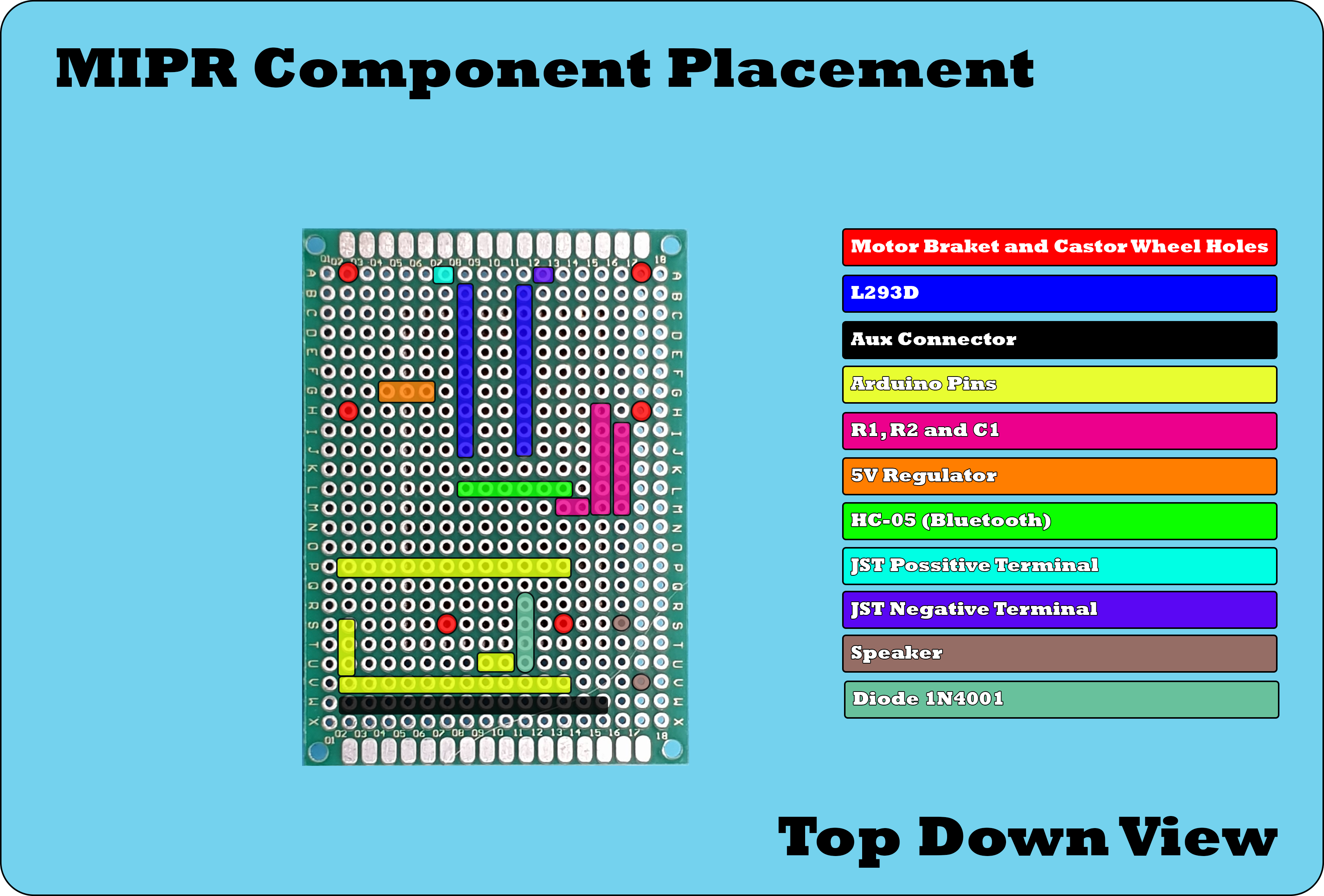
Robot Schematic (Click for an enlarged view)
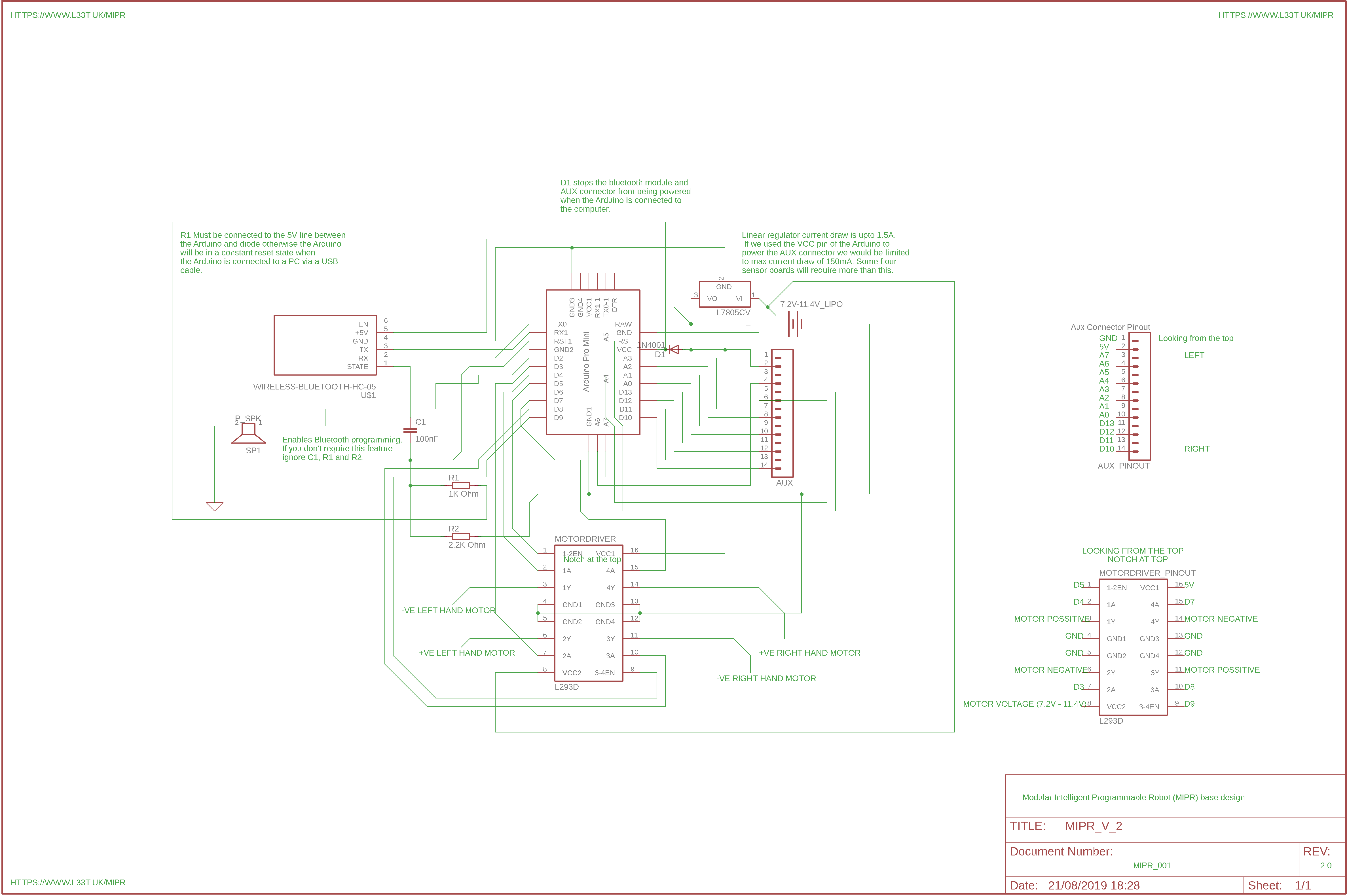
When adding the diode and speaker take note of their polarity. Ensure that the negative side of the diode is connected to the Arduino and that the Arduino’s D2 pin is connected to the speakers positive terminal and it’s negative terminal is connected to ground. Also make sure you understand how to connect the 5V regulator, if this is connected incorrectly it could explode when the battery is added. This datasheet shows the pinout for the regulator. Instead of using a 5V regulator you could use a Buck converter, these are more efficient and will provide more current than the regulator. If you build a sensor board that will draw more than 250mA@12V of current you will need to add a heat sink to the regulator. If this is the case then I would advise using the buck converter rather than the regulator the only downside to this is that the buck converter’s output voltage will need to be setup via a variable resistor.
When adding the motor driver ensure that the notch is at the top and remember that the schematic is a mirror image of your robot. The above schematic is looking at the robot from above and you will be soldering components from below. This means that the pins will be laid out differently. For instance on the schematic the 5V pin on the L293D is at the top right when you solder it from the bottom of the board it will be on the top left and that goes for all of the pins.
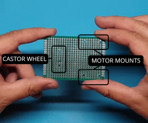
Step 1
Drill holes in the perfboard for the motor brackets and castor wheel.
Use the motor brackets and castor wheel to mark out where the holes need to be drilled. Ensure that the castor wheel is placed 6 rows from the front of the robot as this needs to be placed underneath the Arduino.
Use a 3mm drill bit to drill the holes ensuring that the M2.5 bolts will fit through to secure the wheel and motor brackets.
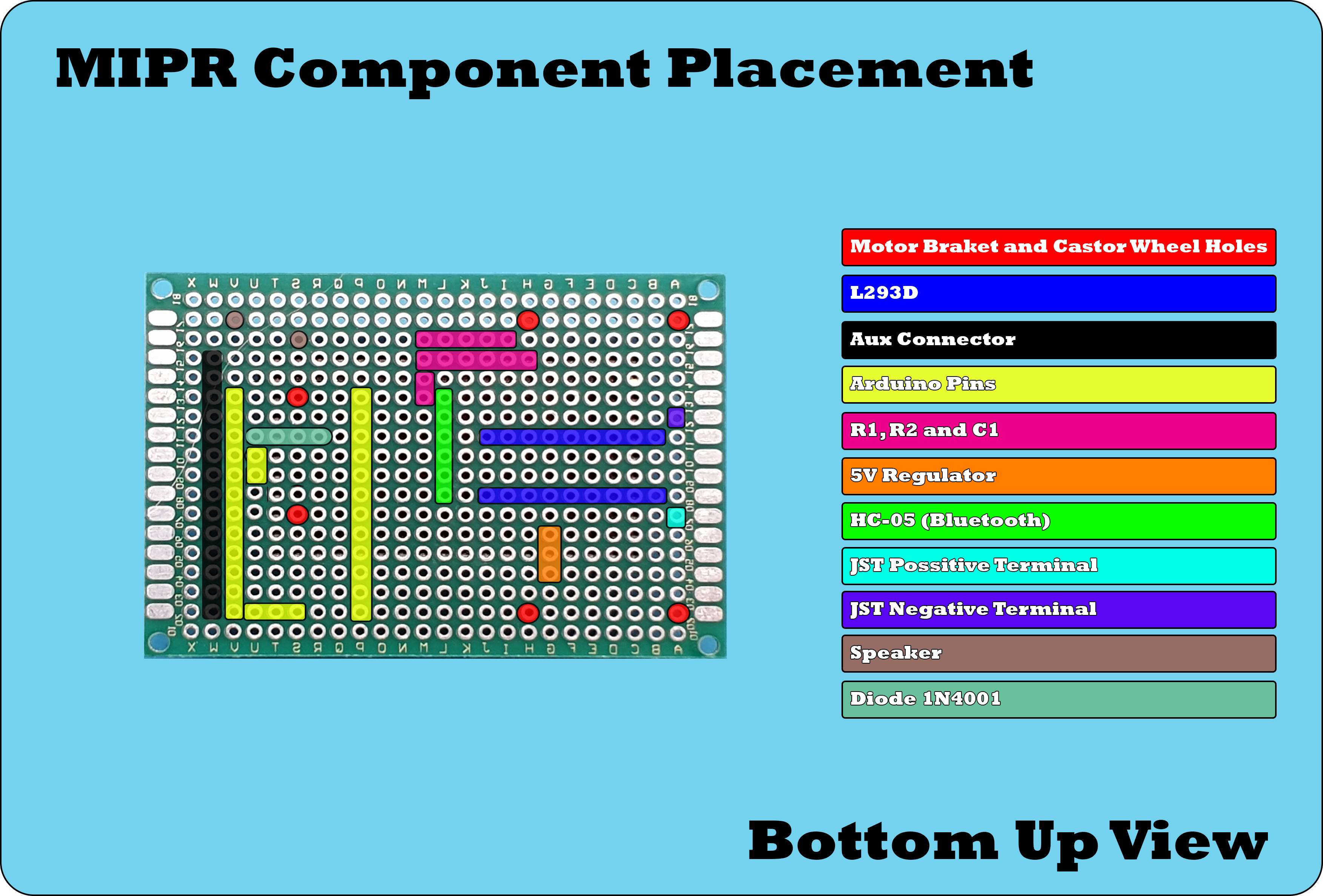
Step 2
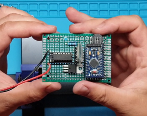
Place the components and solder in place. Start with the larger components first such as the micro controller and motor driver then progress onto the smaller components. Ensure that the Aux connector is mounted on the second row of the perfboard otherwise the expansion boards won’t attach properly. The first pin on the Aux connector should line up with pin 10 on the Arduino. I added the diode underneath the Arduino when adding the diode ensure that the negative side denoted with a grey line goes to the Arduino power pin. This diode will ensure that the Bluetooth module and Aux connector are not powered up if it’s connected to a computer.
Step 3
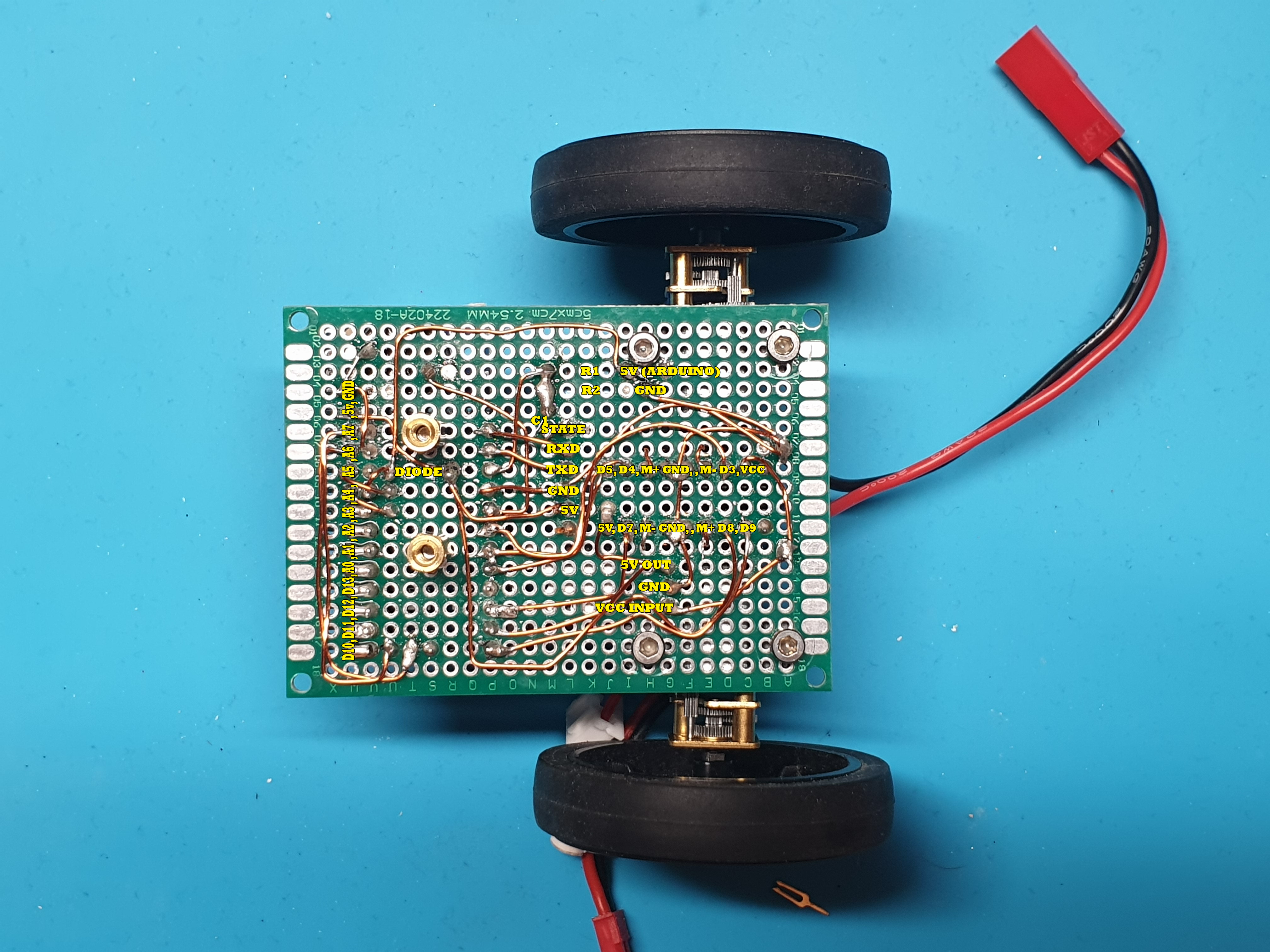
Using the enamelled copper wire connect all the pins as shown in the above schematic. Enamelled copper wire has a coating on it so the wires can touch without creating a short circuit because of this the coating must be burnt off from the end of the wire with the soldering iron before it can be soldered to the pins. If you watch my YT video you can see me burning off the coating when I tin the end of the wire before soldering to each pin.
I connected the components in the following order;
- First half of the Aux connector
- 5V regulator
- Motor Driver
- Arduino
- Rest of the Aux connector and speaker
Step 4
Find a place to attach the Bluetooth module and connect the pins. I placed the Bluetooth module next to the resistors and capacitor that was also opposite the TX and RX pins. Remember that TX needs to be connected to RXD and RX to TXD also remember to connect the state pin to the capacitor C1 and the Arduino’s reset pin to the other side of C1. This will allow us to program the Arduino over Bluetooth.
Step 5
Add castor wheel and motors. Solder the motors to the wires connected to the motor driver and secure using the motor brackets. I soldered the motors to the wires then added the motor brackets. Ensure that the polarity of the motors are the same as the diagram. If they are different then the motor driver code will need to be altered when we write it in the next tutorial.
Step 6
Insert battery and ensure that the Bluetooth module and Arduino powers up. I glued the battery onto the motor brackets and glued the wheels as mine were a little slack.
The below picture shows the completed robot and various interconnections, it’s not very pretty however it is a great starting point when learning about robotics and programming. When sensor boards are added the castor wheel will be moved onto the sensor board and the robot will be twice as long.
A speeded up video of me making the Robot
Amendment to the You Tube Video
When I made the above video I installed the 5V regulator the wrong way around. I don’t know how I did this as I double checked all interconnections when I was making the video. I have amended the YouTube tutorial video to show this but for clarity I have included images below;
This is how I installed the 5V regulator and it’s incorrect. If you install it like this it will pass the VCC to the output with around 1v drop, This will cause instability and if you use a 3 cell lipo or the battery board the robot will become unresponsive.
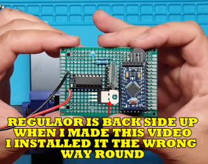
This is how the regulator should be installed, with the back side facing up. If you don’t want the regulator upside down then you can install as above and swap the input and output interconnections on the back.
What Next!
We now have the basics for a rover type robot. It can’t do anything at the moment because we need to write software that will give it some functionality. In the next tutorial we will write software that will enable us to control the robot over Bluetooth and after that we will make various sensor boards that will give the robot more functionality such as obstacle avoidance, line following and light seeking. I will also show you how to create a battery board that will allow us to use a single cell LiPo battery to power the robot allowing us to charge the battery over USB. I will also show you how the robot can be programmed over Bluetooth instead of having to plug the Arduino into your computer.