NOTE: This tutorial shows you how to make a line following sensor board for use with MIPR. If you want to make a line following sensor board for a different robot this tutorial can still be used with the supplied code however you will need to modify the code to enable it to work with your robot.
MIPR in action following an intermediate track using this sensor board;
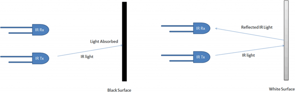
We will make a line following sensor board using 5 TCRT sensors to detect the line. These sensors detect the level of infrared light reflected from a surface. They consist of 2 parts; an infrared LED and a infrared photo-transistor. The below diagram shows what happens when the sensors are over black and white surfaces;
TCRT 5000 Sensor
We can hook these up to the Arduino analogue pins to detect the amount of infrared light detected. We can then use this information to determine if the sensors are over the white background or a black line. Once this is done MIPR can decide what to do; either move forwards, backwards, left, right or to stop. This should result in MIPR following the line.
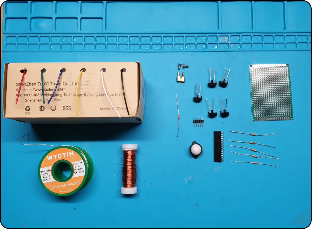
Required Components
7cm * 5cm perfboard
5 * 4.7K ohm resistors or 5 * 470 ohm resistors for the high power version
220 ohm resistor or 1 * 20 ohm resistor for the high power version
14 pin female header 2.54mm pitch
5 pin male header for battery board
Enamelled wire or hookup wire
Castor wheel
Solder
1cm stand offs and crews for the castor wheel
Required Components
Tools Required
Soldering Iron.
Snips.
Solder.
Solder sucker.
Vice/jig to hold the circuit board.
Drill.
3mm Drill bit.
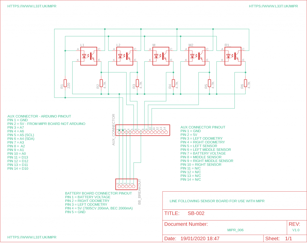
Circuit Diagram
Line following sensor board SB002
High Power vs Low Power
The version of the sensor board shown in the video and schematic is the low power version. This version works really well and each TCRT emitter consumes 4mA of power, however due to this low current draw little IR light is emitted making interference a problem in high noise areas such as outdoors. If your going to use the board in high noise areas use the high power configuration where we supply 50mA to each TCRT emitter. The draw back to this is that it consumes a lot more power so your battery won’t last as long and you will need to change your linear regulator in MIPR for a BEC. If you don’t do this the linear regulator will overheat and cut out. If you install a BEC ensure that you set it’s output to 5V.
To configure the board in high power mode swap the 220 ohm resistor for a 20 ohm resistor and the 4700 ohm resistors for 470 ohm resistors.
Connect the components in accordance with the above diagram. A YouTube video can be seen below showing you how to make the board or you could buy a ready made board from out E-bay shop.
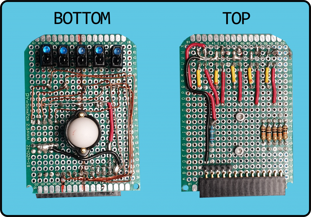
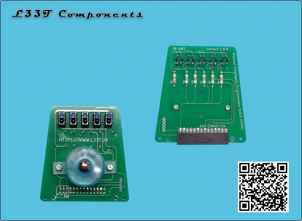
The Completed Sensor Board
Line Following Sensor Board
I designed a PCB version of this board to make prototyping easier. I will order some and add them to my E-Bay shop if there’s enough interest.
Line Follower PCB
Line Following Code
To put MIPR into line following mode open serial monitor and connect to MIPR. Type a capitol O for Oscar and when asked to select a mode select either 6, 7 or 8. The modes are as follows;
6 = Simple LF algorithm
7 = More complex LF algorithm
8 = PID LF algorithm
Once the algorithm is selected MIPR will restart, you will need to put MIPR over a clear part of track for the sensors to calibrate, once calibration is complete MIPR will beep twice. This will take around 5 seconds.
In order for the below code to work download all of the code from our GitHub Repo, unzip it then go into the Version_0_6 folder open any of the .ino files in Arduino IDE then upload the code to your robot. The code uses multiple tabs with code from previous tutorials that have been omitted from this page.
/* * Line Follower Module Verison 0.1 SB-002 * https://www.l33t.uk/arduino_projects/mipr/ * Copyright David Bradshaw 2019 * * This is designed for tracks that use black lines on white background * * The below code uses absolute values from the sensor board and for the code * to work you will need to use the resistor values from the tutorial for either * the Low Power or High Power board. If you use different valued resistors * you will need to convert the values; for the below code to work the baseLine * values will be between 250 and 450, if your baseLine values are 800 for instance * you will have to divide all sensor values by at least half for them to work with this code * * Resistor values should be; Low Power: R1 220 Ohms, R2 - R6 4700 Ohms * High Power: R1 20 Ohms, R2 - R6 470 Ohms (7805CV must be replaced with a BEC due to current draw) */
#include <PID_v1.h>
int L1 = A5; //Outer Left int L2 = A4; //Inner Left int M = A2; //Middle int R2 = A1; //Inner Middle int R1 = A0; //Outer Middle
Setpoint = 0; //turn the PID on leftPID.SetOutputLimits(minLimit, maxLimit); leftPID.SetSampleTime(5); leftPID.SetMode(AUTOMATIC); }
//Simple line follower using just 2 sensors L2 and R2. You need a fairly thick line for this to work properly. //The robot will use absolute values for the speed of each motor not reacting to the environment just using simnple //if then else statements to navigate the track void simple_LF(int leftVal, int rightVal) { int leftMax = leftVal + (leftVal * 0.2); //Tolerance of 20% to make the robot less jerky int leftMin = leftVal - (leftVal * 0.2);
if (rightVal > leftMin && rightVal < leftMax) //If the left and right values are within 20%, go forward { Forwards(100, 100); } else if (leftVal > rightVal) { Right(50,50); } else if (rightVal > leftVal) { Left(50,50); } }
//A simple line follower using L2 and R2 sensors //The speed is adjusted depending on the difference between left and right values void simple_LF_M(int lftAv, int rgtAv, int lrErr) { baseSpeed = 96; //base speed int minSpeed = 0; //Minimum motor speed int maxSpeed = 255; //Maximum motor speed when using low power sensor board //int maxSpeed = 150; //Maximum motor speed when using high power sensor board
int lftSpeed; int rgtSpeed;
//Our goal is to get lrErr to 0 //if it is negative then the robot needs to turn left (left side over the line too much) //if it is possitive then the robot needs to turn right (right side over the line too much)
//lrErr = lrErr * 0.8; //Only use for high power sensor board
if(lrErr > 0) // turn right if the error is possitive { lftSpeed = baseSpeed - lrErr; rgtSpeed = baseSpeed + lrErr; } else // turn left if the error is negative or 0 { lftSpeed = baseSpeed + abs(lrErr); rgtSpeed = baseSpeed - abs(lrErr); }
//Make sure we are above the minimum speed and below the maximum speed if (lftSpeed < minSpeed){lftSpeed = minSpeed;} if (rgtSpeed < minSpeed){rgtSpeed = minSpeed;} if (lftSpeed > maxSpeed){lftSpeed = maxSpeed;} if (rgtSpeed > maxSpeed){rgtSpeed = maxSpeed;}
float nFactor = 1.8; //If this value is set too low the robot will be very jerky //if the speed is nFactor% higher than the base speed then turn left or right, this will produce a sharper //turn than the Forwards function as it will turn one motor forwards and the other backwards to produce the //sharp turn. if(lftSpeed > float(float(baseSpeed) * nFactor)) { Left(lftSpeed, rgtSpeed); } else if(rgtSpeed > float(float(baseSpeed) * nFactor)) { Right(lftSpeed, rgtSpeed); }
else { Forwards(lftSpeed, rgtSpeed); } }
//Complex line follower using a PID algorithm, error tracking, line prediction and all left and right sensors void complex_LF(int leftOVal, int leftMVal, int midVal, int rightMVal, int rightOVal, int lrErr) { // P - Proportional an amount to multiply the error by // I - Integral the sum of previous errors // D - Derivative the speed at which we react to errors
/* * For this PID the setpoint will always be 0 i.e. no error between the left and right side */
float scaleFactor = 1 / float(maxLimit); float ETV; //Error Tracking Value ratio
int leftAv = leftOVal + leftMVal / 2; int rightAv = rightMVal + rightOVal / 2; int lrAv = leftAv-rightAv;
Input = lrAv;
int lftSpeed; int rgtSpeed; int errThreshold = 30; int upperThreshold = 50;
leftPID.Compute();
if (abs(Output) > upperThreshold) { if (baseSpeed > 55) { baseSpeed = baseSpeed - 20; } } if (abs(Output) < errThreshold) { if (baseSpeed < 200) { baseSpeed = baseSpeed + 10; } }
ETV = 1 - (scaleFactor * float(abs(Output)));
//We're using the PID output to calculate the direction and motor speed //This can cause issues when direction change happens quickly due to the //lag built into the PID values. To combat this we will use a vector predict array //Please note that Output will be opposite to Input for instance if Input is //possitive Output will be negative if (Output < 0) // turn left if the error is negative { lftSpeed = (baseSpeed*ETV) + (ETV * abs(Output)); //Slower wheel rgtSpeed = baseSpeed + abs(Output); //Faster wheel prevDirectionArray[directionCounter] = 0; } else if (Output > 0) // turn right if the error is possitive { lftSpeed = baseSpeed + abs(Output); //Faster wheel rgtSpeed = (baseSpeed*ETV) + (ETV * abs(Output)); //Slower wheel prevDirectionArray[directionCounter] = 1; } else { lftSpeed = baseSpeed + abs(Output); rgtSpeed = baseSpeed + abs(Output); }
int maxSpeed = 255; //Maximum motor speed
if (lftSpeed > maxSpeed){lftSpeed = maxSpeed;} if (rgtSpeed > maxSpeed){rgtSpeed = maxSpeed;}
void LFHandler(int mode, boolean fullTele) { //Check to see if this is the first run, if so calibrate the sensor board if (firstRun == true) { sensor_Cal(); firstRun = false; }
//--------------------------------------------------------------------------------------------------------------------------------------------------------------- //THE BELOW CODE IS ALL ABOUT DETECTING A LINE. IF THE LINE IS THERE THEN THE ALGORITHM WILL BE EXECUTED OTHER WISE THE ROBOT WILL STOP AND TURN ON THE SPEAKER //---------------------------------------------------------------------------------------------------------------------------------------------------------------
boolean detectLine = false; //can we see a line
//Compare readings from all sensors to see if a line is present we should have a decrease of at least 10% if we can see a line float lineThresh = 0.90; //This value might need tuning depending on the surface
if (lftAv < 50 && rgtAv < 50) //No IR detected so we are either in a black surface, upside down or theres a thick cross road { //no floor can't be detected detectLine = false; speaker_on(); } else if(lftAv > rgtAv) //Line could be on the right if the robot { if (float(float(rgtAv) / float(lftAv)) > lineThresh ) { //No line detected check middle sensor if (checkMid(midVal, lftAv, rgtAv) == true) //No line detected in the right side so check the middle sensor { //line detected detectLine = true; } else { detectLine = false; } } else //RIGHT SENSORS OVER THE LINE { //line detected detectLine = true; } } else if(lftAv < rgtAv) //Line coule be on the left of the robot { if (float(float(lftAv) / float(rgtAv)) > lineThresh ) { //No line detected check middle sensor if (checkMid(midVal, lftAv, rgtAv) == true) //No line detected in the left side so check the middle sensor { //line detected detectLine = true; } else { detectLine = false; } } else //LEFT SENSORS OVER THE LINE { //line detected detectLine = true; } }
//--------------------------------------------------------------------------------------------------------------------------------------------------------------- //------------------------------------------- END OF LINE DETECTION STUFF --------------------------------------------------------------------------------------- //---------------------------------------------------------------------------------------------------------------------------------------------------------------
if (detectLine == false) //No line detected reverse the robot and sound the speaker { if (opMode == '8') { baseSpeed = 45; if (prevDirection > (direcitonCntr_MAX /2 )) { Left(50,50); } else if (prevDirection < (direcitonCntr_MAX /2 )) { Right(50,50); } else if (prevDirection == (direcitonCntr_MAX /2 )) { softStop(); Backwards(42,42); } } else { softStop(); Backwards(42,42); } speaker_on(); } else //We have a line so execute the correct algorithm { if(mode == 1) //Simple LF { speaker_off(); simple_LF(leftMVal, rightMVal); } else if (mode == 2) //Intemediate LF { speaker_off(); simple_LF_M(lftAv, rgtAv, lrErr); } else if (mode == 3) //PID { speaker_off(); complex_LF(leftOVal, leftMVal, midVal, rightMVal, rightOVal, lrErr);
} } }
boolean checkMid(int midVal, int lftAv, int rgtAv) { float lineThresh = 0.95; //This value might need tuning //Average left and right values here for simplicity if (float(float(midVal) / float(((lftAv + rgtAv) / 2))) > lineThresh) { //No line detected return false; } else //MID SENSOR OVER THE LINE { //line detected return true; } }
//Returns raw value from a sensor int getRawSensorVal(int sensor) { return analogRead(sensor); }
//Returns calibrated value from a sensor int getCalSensorVal(int sensor) { float sensorVal;
//Calibration routine to calibrate the sensors accounting for impedance mismatches in the circuit //and for IR reflectance properties of different materials. void sensor_Cal() { //One beep indicates that Cal is about to start speaker_on(); delay(450); speaker_off();
Serial.println("Put all sensors over a white background and wait for a beep"); delay(500);
int bechmarkM = 0; //Benchmark value all other sensors will align themselves with this value
int itterations = 250; long averageVal = 0;
//get middle average value for (int ii = 0; ii < itterations; ii++) { delay(1); averageVal = averageVal + (long)getRawSensorVal(M); } bechmarkM = averageVal / itterations;
long averageValL1 = 0; long averageValL2 = 0; long averageValR1 = 0; long averageValR2 = 0;
//Bias values that will be used to align the senor values for (int ii = 0; ii < itterations; ii++) { delay(1); averageValL1 = averageValL1 + (long)getRawSensorVal(L1); averageValL2 = averageValL2 + (long)getRawSensorVal(L2); averageValR1 = averageValR1 + (long)getRawSensorVal(R1); averageValR2 = averageValR2 + (long)getRawSensorVal(R2); }
//Calculate the bias as a percentage L1_bias = (float)bechmarkM / (float)averageValL1; L2_bias = (float)bechmarkM / (float)averageValL2; R1_bias = (float)bechmarkM / (float)averageValR1; R2_bias = (float)bechmarkM / (float)averageValR2;
baseLineValue = (getCalSensorVal(L1) + getCalSensorVal(L2) + getCalSensorVal(R1) + getCalSensorVal(R2)) / 4; //Baseline value of left and right sensors
if (baseLineValue == 1023) { Serial.println("The sensors are saturated. If you are in an area of high IR activity either shield the robot or use different value resistors on SB-002"); speaker_on(); delay(5000); speaker_off(); executeBTcommand("O"); }
// 2 beeps to indicate that cal has finished speaker_on(); delay(450); speaker_off(); delay(200); speaker_on(); delay(450); speaker_off(); Serial.print("Sensors calibrated, baseline value: "); Serial.println(baseLineValue);
isCald = true; // Delay to allow user to put robot over the line delay(500); }
In the above code I use a function called LFHandler(mode, fullTele), this function is used to detect a line; if a line is present the selected algorithm will iterate otherwise the robot will do something else. In this case the robot will move backwards. This will allow us to evaluate each algorithm separately knowing that the robot will behave consistently.
Algorithm 1 (Mode 6) – A Simple Method
Time to complete track: 10.5 Seconds
This algorithm will compare the readings from the middle left and middle right sensors, it will then compare the values and if the difference is more than 20% of each value the robot will either turn left or right at a constant speed. The steps are as follows;
Get sensor values from the left and right sensors
Calculate the 20% tolerance
If the left and right values are within 20% of each other go forwards at speed 100
Otherwise if the left value is greater than the right value turn right at speed 50
Otherwise if the right value is greater than the left value turn left at speed 50
The 20% figure was used to make the robot less jerky and to ensure that it behaved as expected (due to the program loop taking less than a millisecond to execute). This is the simplest line following algorithm that we can make and as a result it is very slow and jerky. The robot will gyrate from left to right as it over corrects itself to try and stay on the line. You can change the values to see how it affects the robots behaviour. For instance you can change the speed of the turns, the forwards speed and the tolerance to see what happens.
The below video shows MIPR operating in this mode;
Algorithm 2 (Mode 7) – An Intermediate Method
Time to complete track: 5.9 Seconds
The second algorithm is similar to the first however it is much smoother and faster. With this algorithm we take readings from the 2 left and 2 right sensors, we then average the reading and calculate an error value. This error will be the difference between the left average value and the right average value. We then look to see if this error is a negative number or a positive number. We then drive to robot forward using the error values for the motors speed. Either adding the error to the base speed or taking the error away from the base speed depending on which way we want the robot to turn.
For negative error values we want it to turn left and for positive values we want it to turn right. Before using these values we check to make sure that they are between the min and max limits. Once this is done we check to see if the errors are within a certain tolerance of each other in this case it’s 1.8 which equates to 80%. If they are we go forward otherwise we turn sharply to the left or right depending on the sign of the number.
The algorithms steps are shown below;
Get sensor values from the left and right sensors
Calculate the average for left and right sensors
Calculate the motor speed using the error values, base speed and sign of the error
Check to ensure that the speed is in between min and max value limits -> if not set the values to the min/max values
Check for a sharp turn -> if so turn left or right depending on the error values sign
Otherwise go forward with new speed values
The below video shows MIPR operating in this mode;
Algorithm 3 (Mode 8) – A PID Algorithm with Error Tracking and Line Prediction
Time to complete track: 4.6 Seconds
This is the most complex algorithm that uses a PID loop and error tracker to control motor speed and a novel way of line prediction in case the sensors can not see the line.
It works in a similar way to the above algorithm where an error is calculated between the left and right sensors. If the robot is over the line the error will be zero. When the error is positive the robot is too far right and when the error is negative the robot is too far left. This error value is fed into the PID loop that will give us an output that is between +200 and -200. This value is then used to calculate the direction that the robot needs to travel. Please note that this direction is opposite to the input so for instance a positive value will mean that the robot is too far left instead. The error value is also plugged into the error tracking formula to calculate the speed of the opposite motor and recalculate the base speed.
The formula that I use to calculate the error tracking value is: 1 – (scaleFactor * float(abs(Output)))
Where the scaleFactor is 1 / maxLimit in this case it is 200 so the sacale factor is 0.005.
This error tracking value is then multiplied by the PID output and base speed to set the value of the slower motor and the PID output is added to the base speed to set the value of the faster motor. This will allow the robot to take tight turns by having a large difference between motors when the error is large and a small speed difference between motors when the error is small.
I also adjust the base speed when the error is either large or small. When the error is large the base speed will be reduced and when the error is small the base speed will be increased allowing the robot to go faster on straight lines.
Lastly I use line prediction to allow the robot to follow lines that change sharply. This is needed because the robot will not follow lines that change too quickly due to the PID tuning’s adding a lag when the direction is changed. For instance on direction change their can be a 400mS lag between the sensors seeing the change and the PID output adjusting to this change. If the PID tuning’s are altered to stop this the robot will behave erratically and not follow lines as expected. To combat this the robot will remember the previous 20 moves 0 for left and 1 for right. These will be stored in an array that we will constantly cycle through. When the line can not be seen the robot will sum up the array giving a number from 0 to 20. If the result is less than 10 the robot will predict that it will need to move left, if the result is over 10 the robot will predict that it needs to move right and if the result is 10 the robot will move backwards.
This simple but effective line prediction algorithm allows the robot to follow more complex courses by giving it an averaged memory of between 40 – 80mS. The amount of previous moves can be altered in the code by changing the direcitonCntr_MAX variable to a different number.
The below video shows MIPR operating in this mode;
Making a Track
There are many ways to make a line following track but the easiest way is to draw your own. This sensor board uses analogue readings from the TCRT5000 sensors allowing us to have a track with differing line widths without any performance loss. I use a Sharpie Magnum to draw the lines on a roll of paper, I’ve found that this is the easiest and quickest way to get started.