Difficulty: Beginner
Time: 30 Minutes
Code Version: 0.4
We will be adding an Infrared Time of Flight (TOF) sensor to the light seeking/avoiding sensor board. This will allow MIPR to detect objects, once these objects have been detected MIPR will do something. We can make MIPR avoid or follow an object, in fact we will experiment with a few different behaviours when objects are detected by MIPR.
Most tutorials use either Ultra Sonic sensors or infrared photo-resistors such as the TCRT5000. I have decided not to use these sensors due to certain issues that arise when using them. These issues are;
- TCRT5000 sensors have limited range and become unreliable when sun light is present.
- Ultra Sonic sensors become unreliable at angles above 30 degrees.
- Ultra Sonic sensors will block your code for 30mS to 50mS.
Due to the above issues we will use an IR TOF sensor built by ST Microelectronics. These sensors are more expensive however they’re more accurate than anything else on the market and are not affected by interference.
We will use the VL53L1X sensor. This sensor has a range of up to 4 meters and can be configured in many different ways. These sensors have an on board micro controller that will process the received signal taking the burden off the Arduino. We communicate with them using I2C and they have an update rate of 50hz (in short distance mode), that means we can get a new measurement every 20mS and they don’t block your code allowing MIPR to be responsive.
The field of view can be configured and changed from 27 to 15 degrees however if this is done the range will also be decreased. This is possible by changing the region of interest on the sensors. This sensor uses an array of single photon avalanch diodes, in fact it uses a grid of 16*16 SPAD sensors. By turning some of these sensors off we can change the field of view, track objects and calculate vectors.
This sensor uses infrared light with a wavelength of 940nM and as a result the reliability of the sensor can depend on ambient light levels. In very strong ambient light the range of this sensor can be decreased to 73CM. I’ve been using these sensors since they came to market and I have never had any issues with them. They perform better than any other sensor that I have tried. The 27 degree field of view is perfect for MIPPR allowing it to see all objects in front of the robot.
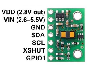
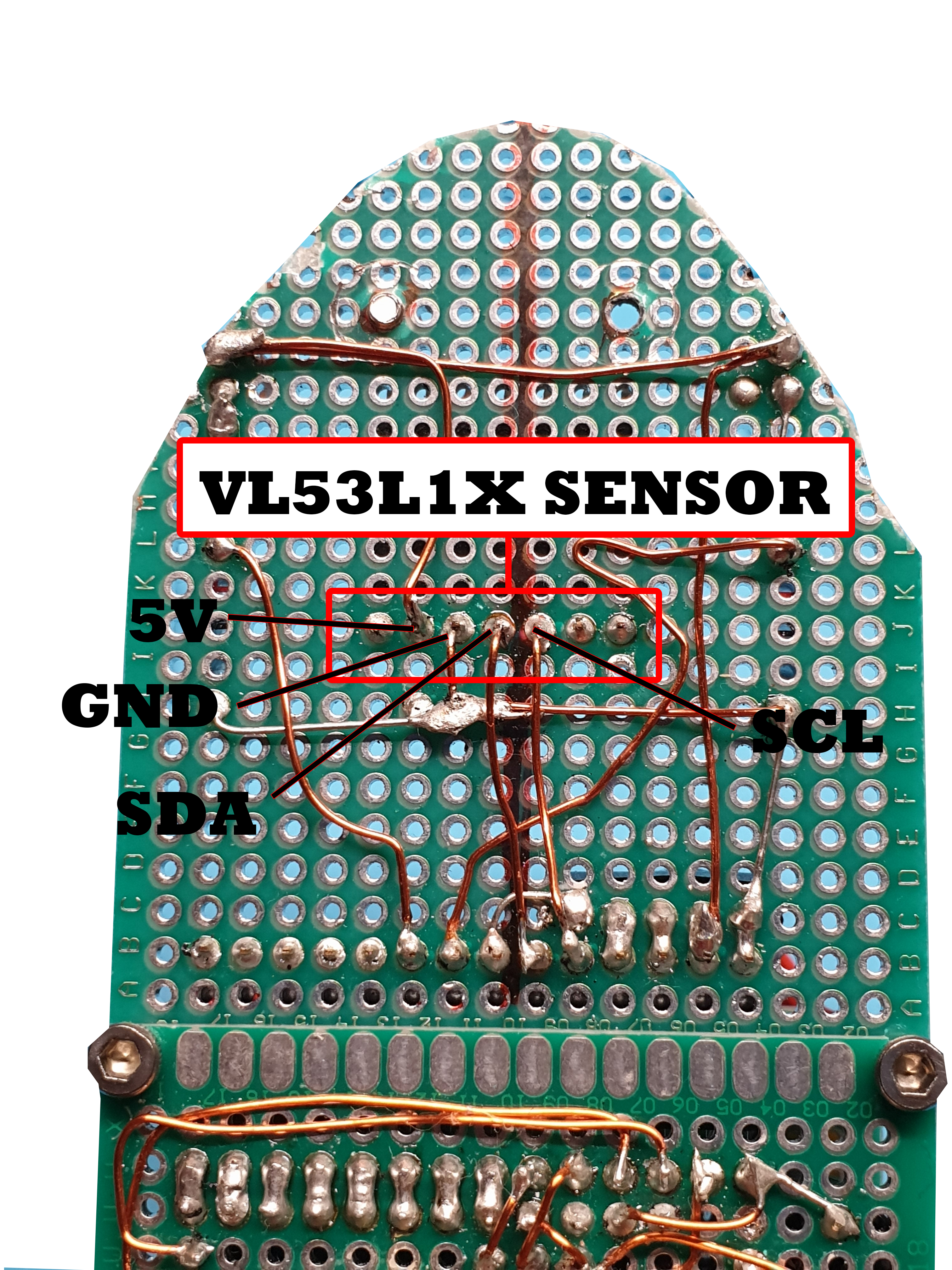
When you purchase the VL53L1X look at the pinout, some manufactures will use a different pinout with the SDA and SCL swapped over. I use the Polou version of the sensor. The below picture shows the layout of the sensors pins.
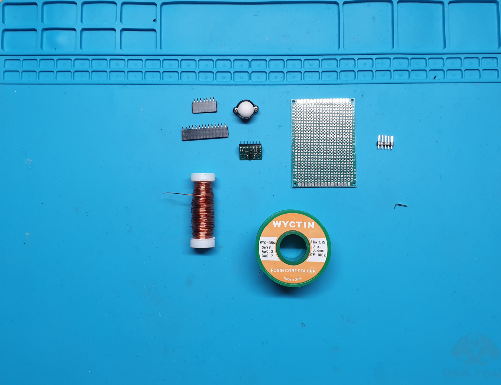
Required Components
If building the board from scratch and not using the light seeking/avoiding board.
- Perf board
- Castor wheel
- 2 * 1cm standoffs (attached to castor wheel on photo)
- VL53L1X sensor (example)
- 2 M2.5 screws
- 14 pin right angled female headers
- 5 pin male headers
- 7 pin right angled female headers
- Enamelled copper wire
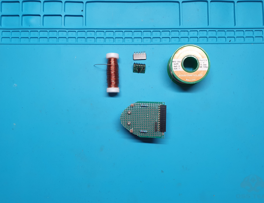
Required Components
When adding the sensor to the light seeking/avoiding board
- 2 * 1cm standoff; these will replace the 0.6cm standoffs.
- 7 pin right angled female headers
- VL53L1X sensor (example)
- Enamelled copper wire
Tools Required
- Soldering Iron.
- Snips.
- Solder.
- Solder sucker.
- Vice/jig to hold the circuit board.
- Drill.
- 3mm Drill bit.
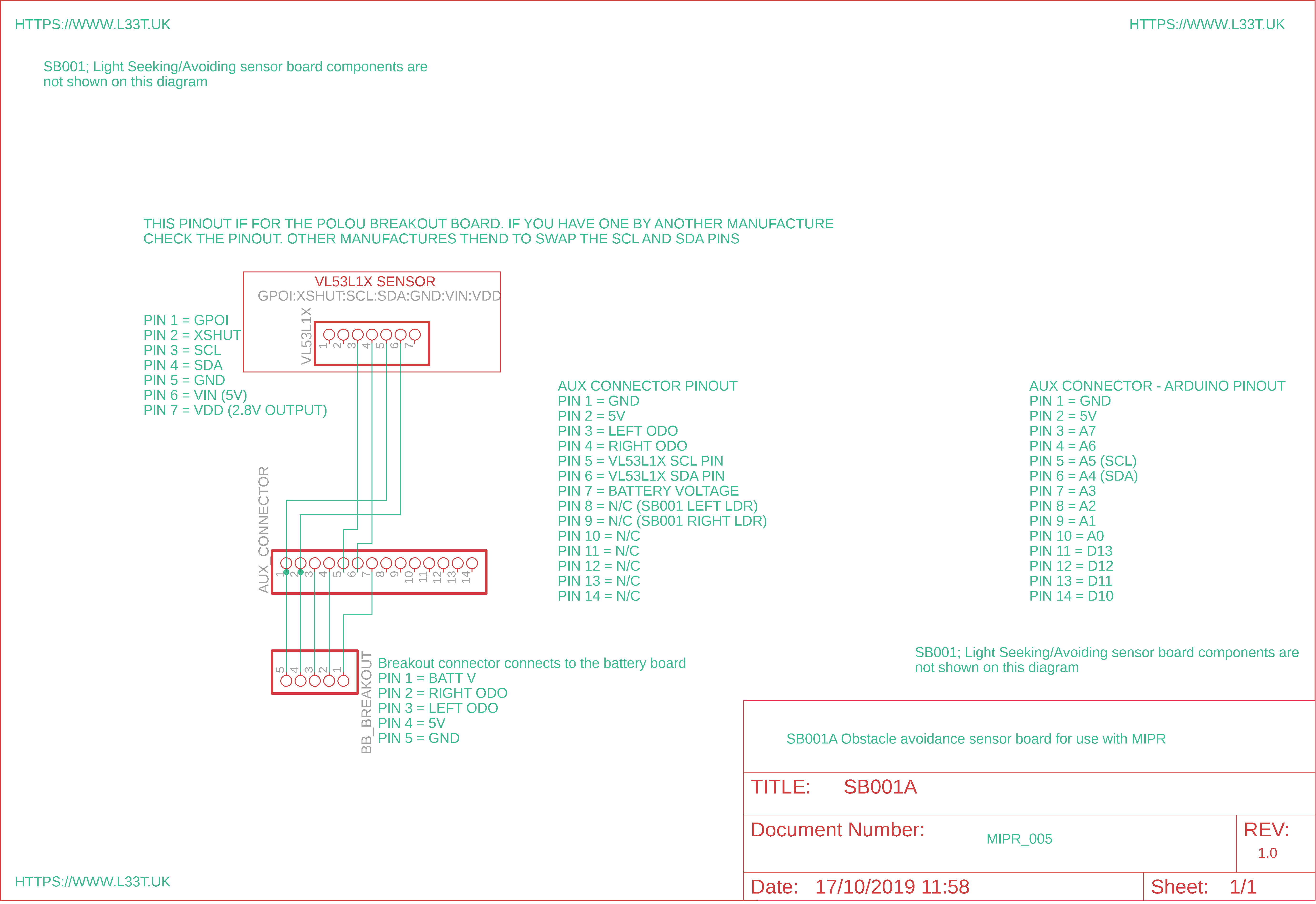
The VL53L1X sensor connects to Arduino over I2C. For I2C to work we use 2 wires, one going to A4 (SDA) and the other goes to A5 (SCL) because of this we will add the sensor to the light seeker/avoider sensor board. The below diagram show a schematic showing how the VL53L1X is connected to MIPR through the auxiliary connector.
The below video will show you how to wire up this sensor board
SB-001 (Light Seeking) with the VL53L1X added
Obstacle Avoidance Code
The below code was added to the previous tutorial to give MIPR obstacle avoidance capabilities. The algorithm is very simple to demonstrate how this board could be used. When MIPR see’s an obstacle that is less than 50cm away it will turn until no obstacles are within 50cm of the robot. It will turn right for a short time and then change direction. This is to stop the robot from getting stuck.
When using the below code ensure that you download the entire codebase from the link on the resources page or from the bottom of this page. For the code to work the Polou VL53L1X library must be downloaded and installed from the following link https://github.com/pololu/vl53l1x-arduino
In order for the above code to work MIPR_CODE.ino and _99_TelPacket.ino were modified so ensure that you download version 0.4 of the code base from the below links.
The above path-finding algorithm is an example of a simple algorithm. If the robot is in a box it will traverse the perimeter of the box. The robot will move forwards until it detects an obstacle. Once the obstacle is detected it will turn until the obstacle can’t be seen by the robot. When no obstacle is present the robot will move forward again.
In order to stop the robot from getting stuck it will move right 20 iterations then left 20 iterations when obstacles are detected. This is a primitive way of stopping the robot from getting stuck by changing its turning direction. Through experimentation you can get the robot to behave differently, for example if we wanted the robot to traverse a maze we would use a different algorithm.
Mode of Operation
The code allows you to operate MIPR in light avoider, seek, radio controlled or obstacle avoidance mode. In order to change the modes turn MIPR on and connect to it using Serial Monitor from Arduino IDE. Once the Serial Monitor is opened type O and press enter (This must be upper case). Serial monitor will ask you which mode you want, type the below number and press enter for the desired mode;
- 0 = Radio controlled mode
- 1 = Light Seeker
- 2 = Light Avoider
- 3 = Obstacle Avoider
Whats Next
Next we will make a line following sensor board to give MIPR even more functionality. Try experimenting with the code for this sensor board and see what you can make MIPR do. I used a simple algorithm in this tutorial perhaps you could improve on it and make MIPR behave differently.