Difficulty: Intermediate (Soldering required)
Time: 2 Hours
During this tutorial we will build a battery board that can be charged over USB, the board will include a power switch and power LED. We will also add some TCRT5000 photosensitive transistors to give us odometry data from the wheels. With this odometry data we can estimate distance travelled and speed of the robot. The battery board will allow you to run MIPR for longer and to charge it over USB that is far more convenient than using a LIPO charger.
The board will be spilt into two parts. The battery board that will consist of a battery, boost circuit, switch and USB charging module. The second half of the board will consist of the TCRT5000 sensors and associated connectivity. This will be known as the odometry module that is part of the battery board 🙂 .
This will be our first attempt at using sensors and it’s a good example of how sensors are not perfect. Noise and differences in circuit design can be a big problem and we must overcome these challenges. To overcome these challenges we calibrate the odometry module, this might look complicated at first but bear with me its not as difficult as it first seems. Its all about aliging the sensors with the wheels for optimum readings.
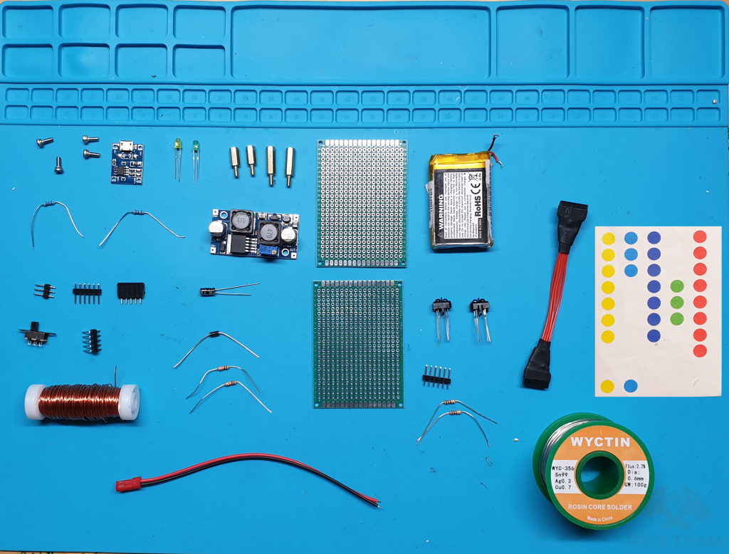
Required Components
Odometry Module
- Perfboard 5cm by 7cm.
- Stickers, preferably round ones with a white back that will cover the holes on the wheels.
- 2 * 100 Ohm Resistor.
- 2* 10K Ohm Resistor.
- 2 * TCRT5000.
- Line of 6 2.54mm headers for inter board connectivity.
- Enamelled Copper Wire.
Battery Board
- Perfboard 5cm by 7cm.
- Single Cell LiPo battery. Dimensions of 49*34*10mm (Example).
- Switch (Example).
- USB LiPo charging module (Example).
- DC – DC Boost Buck Module (Example).
- 2 * LED’s , I used a green one to indicate battery power and a amber one to indicate regulated 5V.
- 2 * 470 Ohm Resistor.
- 8 * M2.5 Standoffs, 4 * 10mm and 4 * 20mm (Example).
- M2.5 Screws to secure standoffs.
- 2.54mm Male Headers (Example). You will need a line of 3 to secure the switch to, a line of 5 for the odometry and a line of 6 for inter-board connectivity.
- 2.54mm Female Headers for inter-board connectivity.
- 5 pin (2.54mm pitch) female to female cable to connect odometry part of the battery board to a sensor board (I made my own).
- Male JST connector.
- 3.3uF capacitor.
- 1N4001 diode.
- Enamelled Copper Wire.
Required Tools
- Soldering Iron.
- Snips.
- Solder.
- Solder sucker.
- Vice/jig to hold the circuit board.
- Hot glue gun.
Part 1 – Building the Odometry Module
This tutorial is split into 2 parts. We will first create an odometry module and set it up, then we will build the battery board. The odometry module consists of 2 TCRT5000 sensors that will monitor the rotation of each wheel. This is done by shining an infrared light on the wheel and measuring the amount of infrared light that is reflected. When the sensor is over the black part of the wheel no infrared will be reflected and when the sensor is over the holes (that will be covered with stickers) more infrared light will be reflected. This will create a frequency modulated pulse train that will change in proportion to the rotational speed of the wheel. We will use this pulse train to get speed and distance information from the robot. We will also use this information to see if the robot is stuck. Ensure that you connect the TCRT5000 sensors correctly and be aware of the orientation of the sensor. The below image shows the layout of the TCRT5000.
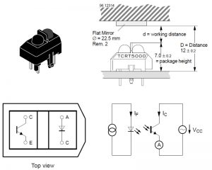
The easiest way to orient a TCRT5000 sensor is to look at the end with the cut off corners. This is the LED part of the sensor that emits IR light. When orientated in the same way as the diagram the top pin is the anode and the bottom pin is the cathode. The other part of the sensor is the sensor that senses the IR light. This acts as a transistor where you have a collector and emitter. The IR light is used to bias the sensor where the more IR light it detects the more current will pass though the sensor just like the base pin of a transistor. When higher current passes through the sensor we will see it as a voltage drop on the input of the Arduino. To achieve this we will use a 10K Ohm resistor and the sensor as a voltage divider by connecting the analog pin of the Arduino between the resistor and the sensor.
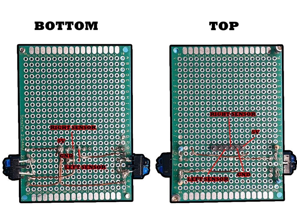
Please Note; the TCRT5000 sensors are mounted to the bottom of the perf board and the rest of the components are mounted at the top of the board. If the sensors are mounted on the top of the board they will not fit inside the wheels.
The below diagram shows how the components are connected to create the odometry module.

In case it’s not entirely clear on the diagram, the 5v line is above the TCRT5000 sensors and the ground line is below them. This means that all connections above the sensors are connected to the 5v line and all connections below the sensors are connected to the ground line.
The IR LED’s can handle 50mA of current. We will use a 100 Ohm resistor to provide the IR LED with 50mA of current (Ohms law I = V/R). This will give us loads of IR light for the sensor to detect. We will use a 10,000 Ohm resistor to control the amount of current on the collector of the sensor. This will make the sensor extremely sensitive to the IR light. If we were concerned about interference we would use a resistor with a smaller value such as 2,000 Ohms allowing more current on the collector of the sensor decreasing it’s sensitivity.
Finished Odometry Module
It doesn’t matter where the resistors or wires are placed. The important thing is that you put the TCRT5000 sensors and the inter-board connector in the same place as me. I placed the resistors at the side of the board to make more room for the battery board components.
Modified Wheels
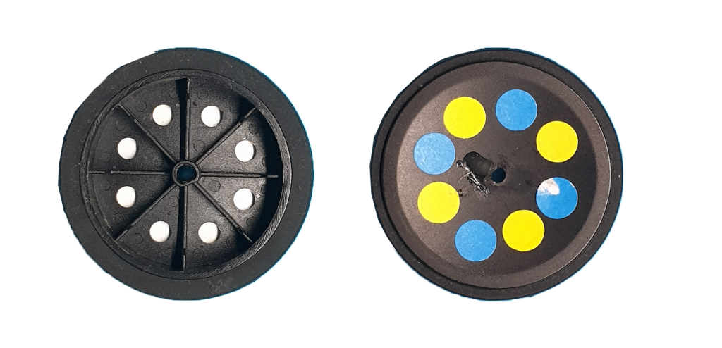
Once the odometry module is complete you will need to set it up ensuring that the sensor is pointing in the correct direction to optimally detect the holes in the wheel. The below video shows you how to do this. Once calibration is complete the data will be saved to the EEPROM. The data will still be available even if a new program is uploaded to the robot. You should re-run the calibration routine when ever the battery board is removed, if the stickers are replaced or if the sensors are misaligned.
Calibration Code Download
If your not using the HC-05 to program MIPR you will need to change the baud rate to 9600 in the code file from the below zip archive. Line 31 reads Serial.begin(57600);. If you’ve not changed the baud rate on the HC-05 this line should read Serial.begin(9600);
Click here to download the code
Calibration Instructions (Watch the video first)
NOTE: When using Telemetry.jar ensure that serial monitor is closed. Only one application can access the comm port at any one time. If Telemetry.jar starts to misbehave press control alt and delete to open task manager then close it down. Reopen Telemetry.jar and it should work as desired. If Arduino IDE, serial monitor and Telemetry.jar can’t connect to MIPR then close all applications, restart and you should be able to connect.
- Download the zip file from the above link
- Unzip the archive and open one of the Arduino code files.
- If your programming MIPR over USB instead of Bluetooth change the line Serial.begin(57600) to Serial.begin(9600).
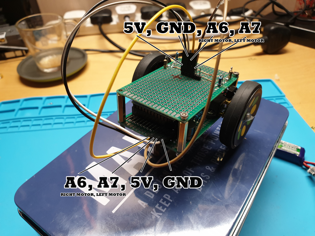
- Connect the Odometry Module (see picture below).
- Turn on your robot.
- Upload the code to your robot. Position your robot so the wheels are not in contact with the ground. You can hold it or put it on a stand.
- Open the serial monitor and type C then press enter (it must be in uppercase).
- This will run the calibration routine. If the values returned for mean left and mean right are between 400 and 600 then you don’t need to make any adjustments. However if they’re below 400 or above 600 you will need to move the TCRT5000 sensors slightly either up or down and re-run the calibration procedure. We want the sensors to be in line with the holes in the wheels.
- If you can not get these figures in spec you will need to re-position the TCRT5000 sensors so they are closer to the wheels or try different stickers that will reflect more infrared.
- Once these figures are in spec type P and press enter into the serial monitor, when it asks you for the mode type 1 then press enter. This will put the robot into calibration check mode and run the motors forwards at half speed. Now close the serial monitor.
- Open Telemetry.jar from the download zip and click on “open layout” from the bottom left hand corner. When the dialog box appears select the file named “LEFTRIGHT_ALL.txt”. It will try to connect to your robot and probably fail. Select the correct comm port from the bottom right of the screen and the correct baud rate. For me the baud rate is 57600 because i’m using the HC-05 to program MIPR. If your still programming MIPR over USB then select 9600 as your baud rate.
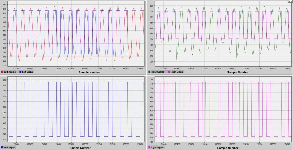
- You should now see a pulse train for the left and right motor. You need to make sure that the digital sampling of the pulse train is accurate it should look like the below picture with all analog waves being accurately sampled and turned into a square wave. If samples are missing go back to step 6 and re-run the calibration routine. When happy with the setup close the Telemetry application and re-open serial monitor. Then press P followed by enter and when prompted press 0 followed by enter. This will put the robot back into default mode.
- NOTE: The sample rate in the below image is set to 250. By default the Telemetry file has a sample rate set to 1000. This means that you will see 4 times more cycles on your readout, what we’re looking for here is that the analog waveform is sampled accurately and no cycles are missed. See the above video for more details.
If you have issues in the future with the odometry module then redo this procedure to ensure that it is calibrated properly. If the stickers start to come off or get dirty the routine must be repeated to ensure that you get accurate odometry measurements.
MIPR with the odometry module attached and setup, I put the components to the side of the board to make room for the battery board components. These components will be the battery, switch, LED, capacitor, battery charging module and DC to DC boost converter.
Design decisions; We could have captured this odometry data using interrupts. This would have been a better design however for this to have worked we would have needed to add more hardware such as Schmitt triggers to sample the data. These triggers can be difficult to setup and we already used the Arduino interrupt pins for other things. Instead I decided to sample the analog waveform in software and use a polling loop to look for changes. If the main program loop takes more than 4mS to execute the odometry module will loose accuracy.
Part 2 – Making the Battery Board
Now the Odometry Module is complete it’s time to make the battery board. This will allow us to provide the motors with 12 volts giving MIPR a greater top speed and we will be able to charge the LiPo battery over USB. The below diagram shows how all of the components are connected.
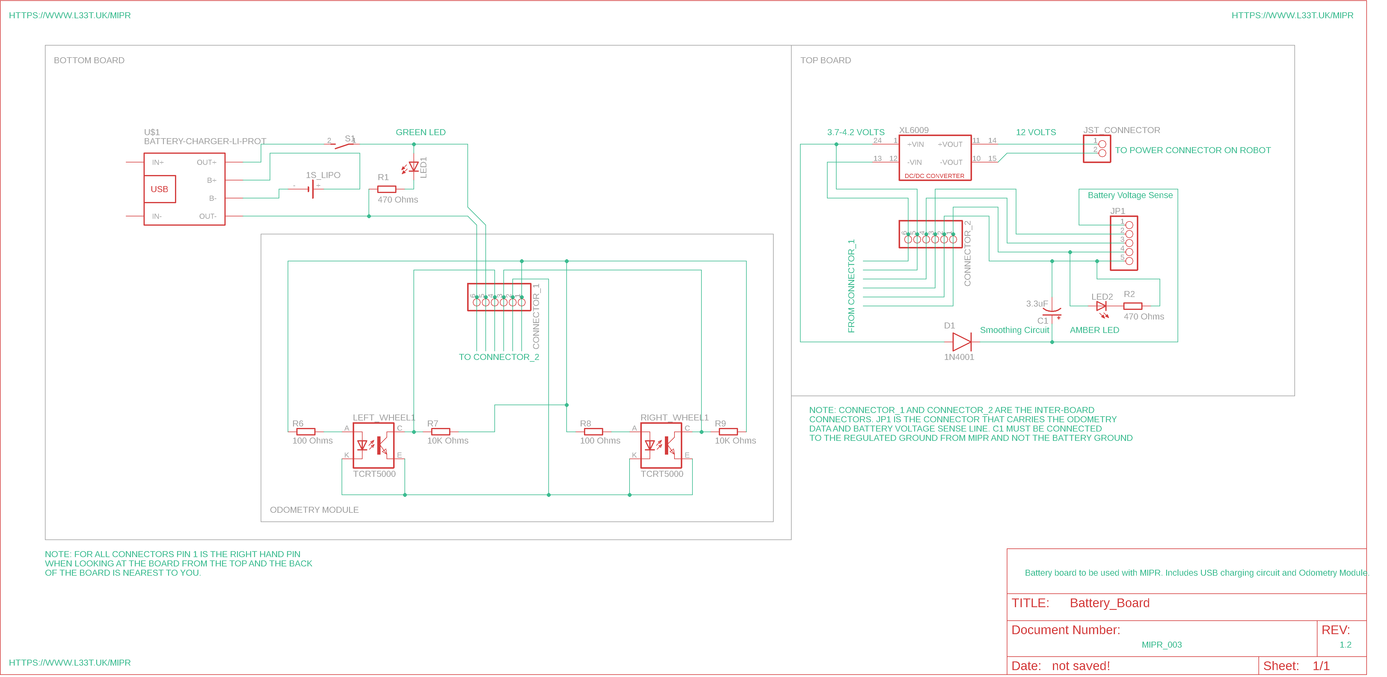
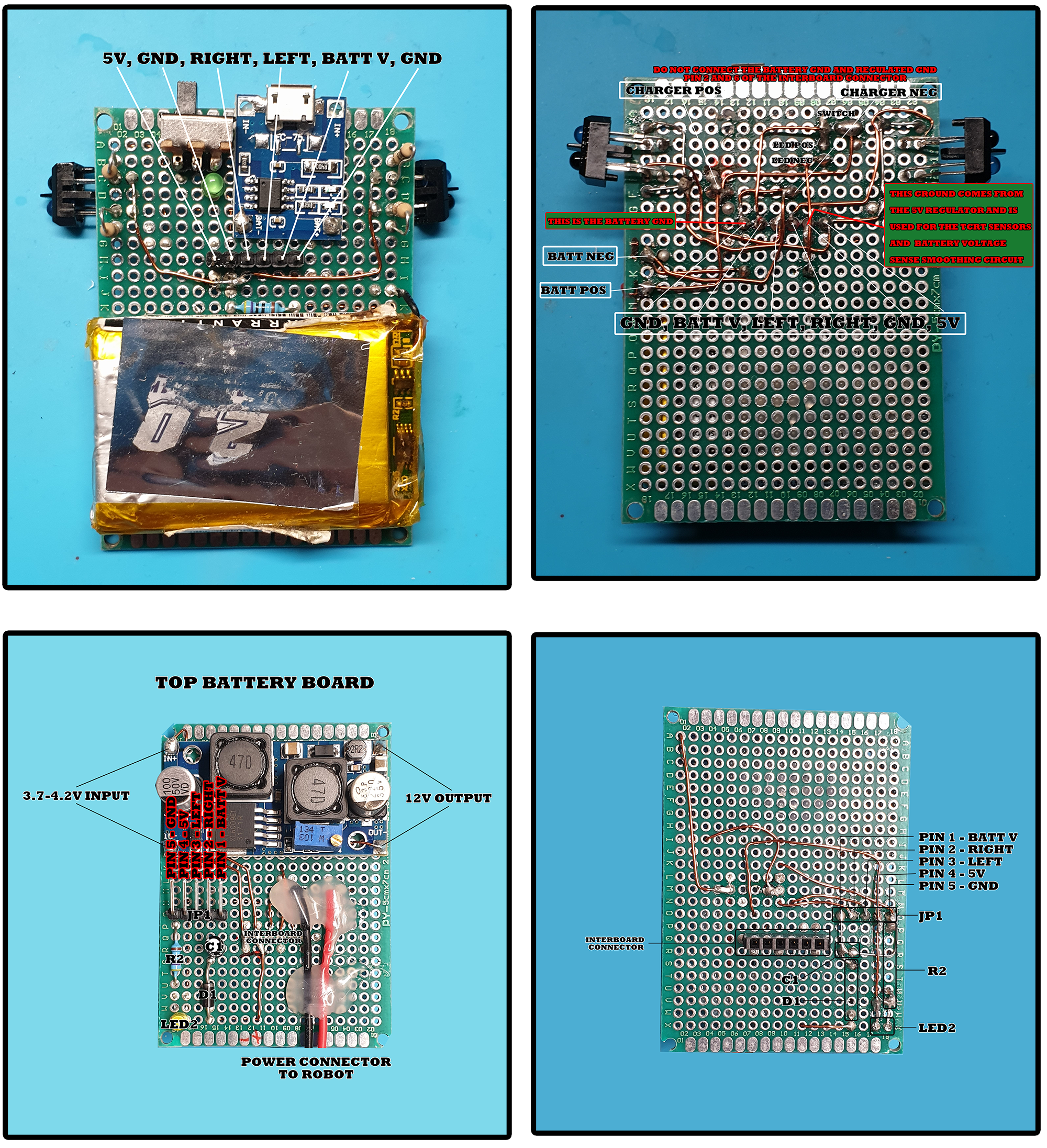
The below video shows you how to make the battery board. Component placement is not critical as long as the inter-board connector is in the correct place. You can use any 1S LiPo battery that will fit however I like to use the one in the inventory as it has built in protection so you don’t need to worry about shorting the contacts.
Battery Board Pictures
Once the board is made you need to set the output voltage to 12v. This can be done using a multi-meter or it can be done using the example code. The below video demonstrates how to set the output of the battery board with a digital volt meter and by using the Odometry Module and looking at the speed of the motors.
Download this code to set the voltage output to 12 Volts in accordance with the above video. If you have a multi meter you don’t need this however you could download the code once your DC voltage is set to 12 volts to ensure that the odometry module is working correctly. If your odometry module is working correctly the left and right motors speed should be in between the red and blue lines on the serial plotter graph (see above video).
Battery Voltage
Use the following code to calculate your battery voltage;
I’ve inserted the above code to explain why I used the figure of 4.6 rather than 5 when calculating each voltage step. MIPR has a convoluted power system making it flexible allowing different battery configurations and different ways to program the robot. To enable this I added a diode on the 5V input to the Arduino, this reduces it’s input voltage from 5 volts to 4.2 volts. This means that the reference voltage inside the Arduino is lower than it should be. Because this reference voltage is incorrect we need to use the figure 4.6 rather than 5. The battery smoothing circuit also interferes with the reading, this is why we use 4.6 rather than 4.2. With no smoothing 4.2 would have been the correct figure to use. You might need to tweak this value for your version of MIPR.
I use the above code in the next tutorial where we create a light following/avoiding sensor board.
Final Word
At this point we have a robot that’s powered by a single cell LiPo allowing us to recharge it over USB. We can program the robot via Bluetooth and the robot has real-time odometry data available so it knows how far its travelled. Next we will be create some sensor boards starting with a light follower and avoider sensor board.