Difficuilty: intermediate
Time: 1 hour
Code Version: 0.3
Building a light seeking and light avoiding robot can be really interesting. There are many ways to program this type of behaviour and with our robot we will use the light measurements to drive the robots motors and decide how fast they should spin.
We will create a sensor board with 2 light dependant resistors, one on the left and one on the right. We will use these LDR’s to sample the amount of light then use this value to decide how fast the motors should spin. We will then use the inverse of this for light avoiding mode.
Required Components
- 2 * Light Dependant Resistors
- 2 * 2.2K Ohm Resistors
- 5cm * 7cm Perfboard
- Castor Wheel
- 2 * 6mm M2.5 standoffs
- 2 * M2.5 screws
- 14 pin 2.54mm female header (for aux connector)
- 5 pin 2.54mm male header (for battery board)
Required Components
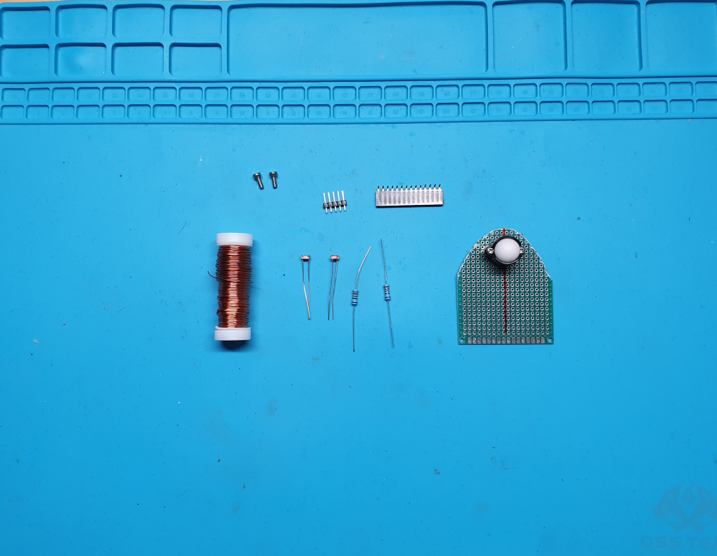
I have already attached the castor wheel and standoffs to the perfboard in the above image.
Tools Required
- Soldering Iron.
- Snips.
- Solder.
- Solder sucker.
- Vice/jig to hold the circuit board.
- Drill.
- 3mm Drill bit.
We will use the light dependant resistors and 2.2K ohm resistors as a voltage divider. The resistance will decrease as the light levels increase this will give us a higher voltage from the output of our voltage divider. We will have 2 of these one for the left side and one for the right. As mentioned earlier my code will set the speed of the motors depending on the intensity of the light sensed by the LDR’s. You can experiment with the code and try different code implementations to make the robot behave differently.
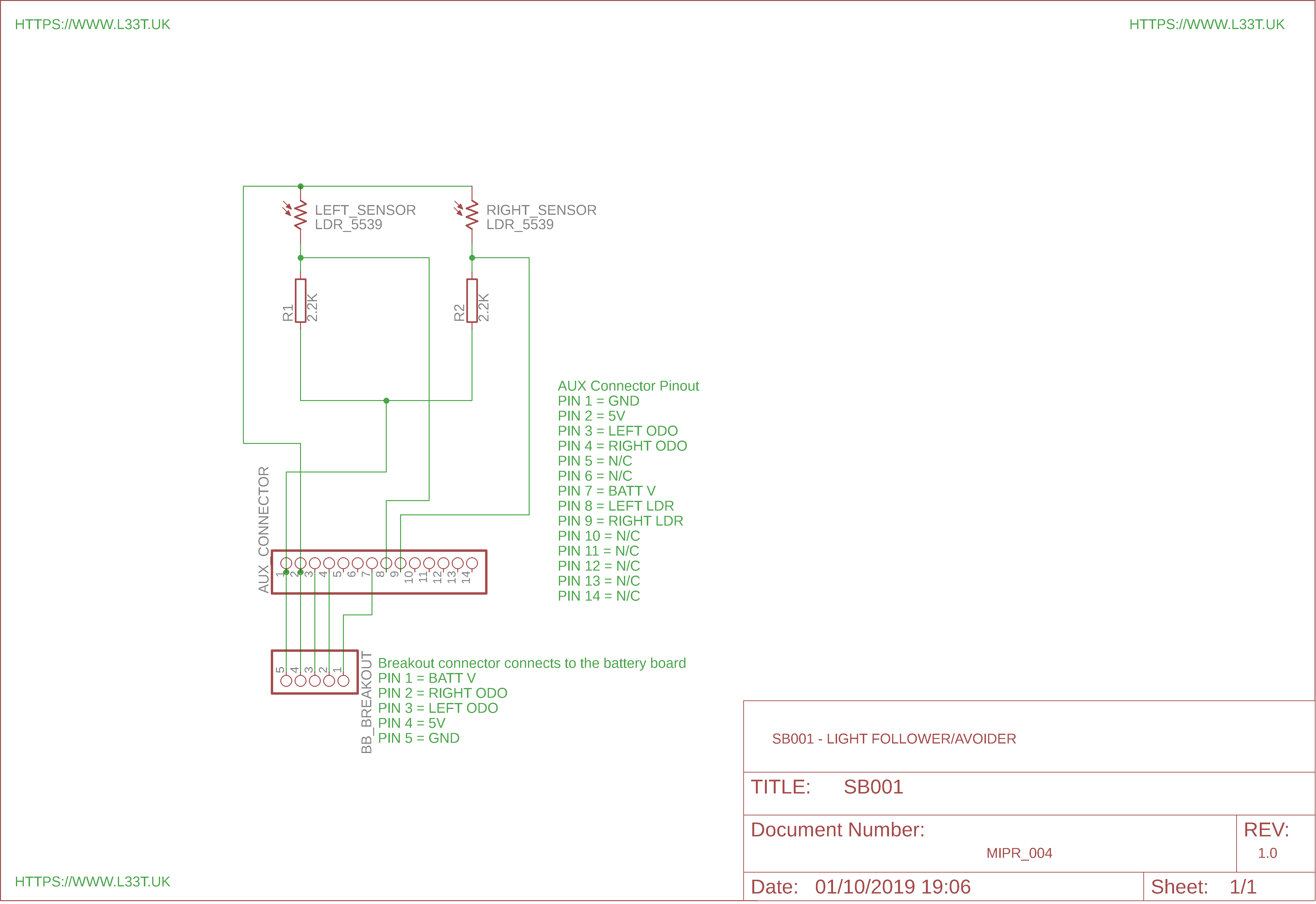
Below is a schematic of the sensor board;
The below video demonstrates how to make the sensor board;
When I wrote the code for this tutorial I used different tabs in Arduino IDE to implement different functions, because of this you will need to download the code from our GitHub repo by following the link on the bottom of this page. If you have an Odometry Module installed ensure that you change OdoMod_Installed to true on line 14 of the Version_0_3.ino file. Once done unzip the code and upload to MIPR.
To keep this page uncluttered I will insert the sensor board code below. To download the full code go to our GitHub repo by following the link at the bottom of this page.
By looking at the code you can see that we use the direct values from the LDR’s to set the motors speed. If the sensed light is of a similar intensity the robot will move forwards. If it’s not the motor on the side where the light is the brightest will stop and the motor on the opposite side will spin at a speed proportional to the light. The opposite side motor is stopped to make the robot more responsive. In light avoidance the behaviour is inverted.
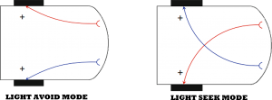
This behaviour was first described by Valentino Braitenberg and this version of MIPR with this code behaves like Braitenberg’s presentation of vehicles. The diagram below shows whats going on in the robot and how the light intensity is fed back into the motors to control their speed.
This code can be improved on by smoothing the data and making the robot behave in a more predictable way. You could remove the speed light relationship making the robot move in low light situations. For this to work you would need to do some thresholding and calculate ambient light levels.
You will notice that I don’t have any code for light avoid mode this is because I use the function getMotorSpeed() to directly set the motor speed therefore I can switch the arguments for light avoidance mode so the left wheel is coupled with the left sensor and the right wheel coupled with the right sensor;
We use a boolean argument to denote if we’re in light avoid mode because in light avoid mode the robot will move backwards if the light values sensed by the senors is similar where as the robot will move forwards during this condition in light seek mode.
Mode of Operation
The code allows you to operate MIPR in light avoider, seek or radio controlled mode. In order to change the modes turn MIPR on and connect to it using Serial Monitor from Arduino IDE. Once the Serial Monitor is opened type O and press enter (This must be upper case). Serial monitor will ask you which mode you want, type the below number and press enter for the desired mode;
- 0 = Radio controlled mode
- 1 = Light Seeker
- 2 = Light Avoider
The Robot in Action
Finally
Remember to change the baud rate on line 24 to 9600 if you don’t use the Bluetooth module to program the robot and to change the boolean variable OdoMod_Installed to true if you have the odometry module attached.
What Next!
We now have a robot that can do something! it will either follow or avoid light and it will transmit odometry data at the same time. The odometry data is a little jerky at the moment and only updates once every wheel revolution however, over the next few tutorials we will improve on this. The robot also responds to Bluetooth commands that will allow us to remote control it and restart it in different modes. Next we will expand this board by adding a sensor that will detect objects. Almost all tutorials like this on the internet use Ultra Sonic sensors, these sensors are inaccurate and will hang your code for around 30mS. This delay is unacceptable for a real time system such as a robot. To overcome these challenges we will be using an Infrared Time of Flight sensor that will be more accurate and have faster response times. We will then write some code to give MIPR obstacle avoidance abilities.