IMPORTANT: BEFORE APPLYING POWER TO THIS SENSOR ENSURE THAT THE VIN AND GND INPUTS ARE CORRECT. IF YOU HAVE THESE THE WRONG WAY AROUND IT WILL FRY YOUR VL53L0X SENSOR.
The VL53L0X is an infrared time of flight sensor developed by ST-Microelectronics and is part of an IR TOF family of sensors . These sensors are 5V and 3.3V tolerant. An image of the sensor can be seen below;

In this tutorial I will show you how to hook it up to an Arduino micro-controller, we will then write a simple program to get it working. After that I will show you how to hook more than one of these sensors to the same I2C bus allowing you to have multiple sensors connected to a single Arduino. This could be useful for gesture recognition or advanced obstacle detection for robots.
The sensor has a 2 meter range and can detect objects in ambient light as well as in darkness. It has an onboard micro-controller that processes the data, removes noise and outputs the clean data. We can run the sensor in different configurations depending on our requirements and as long as we don’t request data quicker than the sensor can process it the sensor won’t block your code (I will explain this later).
These sensors are better than the ultrasonic ones as they don’t block your code and they can detect objects at all angles and in all conditions. If your designing a robot that needs to sense it’s surroundings these are a good, low cost option.
How it Works
These sensors work by emitting light at a given frequency, for these sensors that frequency is around 318Thz giving us a wavelength of 940nM. This is not visible to the naked eye however it can be seen by a digital camera. The sensor has a single photon avalanche diode (SPAD) array that is a collection of little sensors, when these sensors detect a certain wavelength, in this case 940nM they start to conduct electricity. The VL53L0X will transmit a pulse of infrared light and start a timer. If the light is reflected from an object the SPAD array will detect it and some of the diodes within that array will start to conduct when this happens the timer will stop and the micro controller inside the sensor will do some complex maths to calculate the distance of the object from the sensor. The reason why the maths is complex is because the micro controller will need to take into account noise and interference, once this has been removed it can calculate the distance using the following formula D = (C*T)/2 where C is the speed of light and T is the time taken for the light to reflect back off a target. We divide this number by 2 because the light will go from the sensor to an object and then back to the sensor. RADAR’s use the same principle but with lower frequency RF energy.
The below diagram shows how to connect a single sensor to an Arduino Nano;

As you can see we’re connecting the sensor to the Arduino’s I2C bus, this will allow us to interface with the sensor configuring it and getting data back from it.
Before we can use the sensor we will need to download a library to unlock it’s functionality. There are many libraries available for this sensor on the internet and in this case we will use the library provided by Polou. Go to their GitHub page, click the clone or download button and choose “Download ZIP”.
Now go into Arduino IDE and select the following menu selections;
Sketch -> Include Library -> Add .Zip Library
Then select the ZIP file that you just downloaded from GitHub. The library should now be installed allowing us to program the sensor. You can also install this library using the library manager in Arduino IDE and searching for Polou VL53L0X. Below is some code to allow you to take measurements with the VL53L0X;
You can configure the sensor in different ways to alter the range, increasing refresh rate, accuracy or changing how it takes measurements. You will notice that I request a measurement from the sensor every 100mS giving us a refresh rate of 10Hz. This can be changed but make sure that the refresh rate in milliseconds is greater than the timing budget. If you request a measurement from the sensor before a measurement is ready it will hang your code for around 50mS. To avoid this you can use the output from the GPIO1 pin, this is an interrupt and it goes low when a measurement is ready. By connecting this pin to your Arduino you could wait until the pin goes low and when it does then request a measurement from the sensor.
To find out more about the sensor and library go to Polou’s GitHub page and read the documentation.
Multiple Sensors
These sensors use the I2C bus to communicate with the Micro-Controller. This bus can have up to 127 slaves connected at any one time and as a result we can hook multiple sensors to the same bus. In order to do this we need to bring each sensor online one at a time and configure it’s I2C address, once this is done the next sensor can be brought online, address configured and so on.
To do this we use the XSHUT pin on the VL53L0X sensor. When this pin is set to low the sensor will be turned off allowing us to turn each sensor on one at a time and configure their I2C address.
The below diagram shows 2 sensors connected to the same I2C bus. This can be expanded to as many sensors as you want up to the I2C bus’s maximum which is 127.
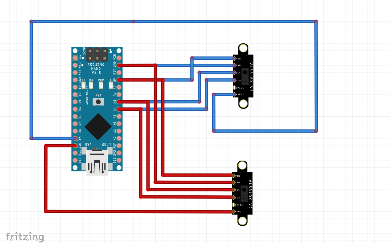
The below code snippet shows you how to turn each sensor on one at a time and configure there I2C address. The default address for a VL53L0X sensor is 0x29 (So don’t use this one or you could have issues).
If you want to support L33T.uk you can purchase this sensor from our E-Bay shop.